
Cylinders
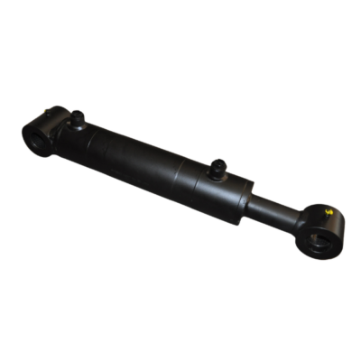
We offer various types of cylinders. Examples of available dimensions:
-
Double-acting cylinder, 20×40, EAF 432, C 245
-
Double-acting cylinder, 30×50, EAF 425, C 95×2
-
Double-acting cylinder, 30×50, EAF 320, C 150 BMF.C/FMF.C
-
Double-acting cylinder, 30×50, EAF 425, C 200 GRBB
-
Double-acting cylinder, 30×50, EAF 700, C 500 VPRF FRAME
-
Double-acting cylinder, 35×60, EAF 367, C 198, bore aligned with ports (GB)
-
Double-acting cylinder, 35×60, EAF 367, C 198, 90° offset bore to ports
-
Double-acting cylinder, 35×60, EAF 367, C 198, 90° offset bore (port width 45)
-
Double-acting cylinder, 35×60, EAF 560, C 340
-
Double-acting cylinder, 35×60, EAF 660, C 440
-
Double-acting cylinder, 40×70, EAF 425, C 210
-
Double-acting cylinder, 40×70, EAF 445, C 220
-
Double-acting cylinder, 40×70, EAF 523, C 220
-
Double-acting cylinder, 40×70, EAF 525, C 300 BF
-
Double-acting cylinder, 40×70, EAF 620, C 345 BDL GB
-
Double-acting cylinder, 50×100, EAF 525, C 300 BF
-
Double-acting cylinder, 50×100, EAF 770, C 380 with 2x Ø60 PAC ball joints
-
Double-acting cylinder, 50×80, EAF 550, C 215
-
Double-acting cylinder, 50×90, EAF 620, C 345 BDL
-
Double-acting cylinder, 65×100, EAF 925, C 700
With cushioning (end-of-stroke damping):
-
Double-acting cylinder, 40×70, EAF 445, C 220, end-of-stroke cushioning BMF.R2/R3
-
Double-acting cylinder, 50×100, EAF 540, C 200, 2x Ø40 ball joints with end-of-stroke cushioning
-
Double-acting cylinder, 50×90, EAF 700, C 400 with end-of-stroke cushioning PAG
-
Double-acting cylinder, 60×100, EAF 850, C 500, 2x Ø40 ball joints with end-of-stroke cushioning
-
Double-acting cylinder, 40×70, EAF 523, C 220 with end-of-stroke cushioning
For other models, please contact us.
More information
Technical Guide: How to choose and measure your cylinder?
Before placing an order, it is essential to master the technical vocabulary to ensure the cylinder perfectly matches your installation. Here are the key terms explained simply.
1. Types of Operation
-
Double-Acting Cylinder: The most common model. Fluid pressure (air or oil) extends and retracts the rod. It has two supply ports.
-
Single-Acting Cylinder: Pressure only moves the rod in one direction (usually extension). The return to the initial position is handled by an internal spring or an external load.
2. Dimensional Glossary
-
Bore: The internal diameter of the cylinder tube. This figure determines the pushing force.
-
Rod Diameter: The diameter of the metal bar that extends from the cylinder.
-
Stroke (C): The maximum distance the rod travels between its fully retracted and fully extended positions.
-
EAF (Closed Centers): This is the crucial measurement for installation. It is the distance between the two mounting points (usually the center of the clevises or eyelets) when the cylinder is fully retracted.
-
EAD (Open Centers): The distance between the two mounting points when the cylinder is fully extended.
-
Cushioning: A system (often adjustable via a screw) that slows the rod at the end of its stroke to avoid sharp impacts against the cylinder ends, thereby extending its service life.
3. Measurement Diagram
To avoid errors, use a caliper and follow these measurement points:
| Dimension to measure | Symbol | Description |
| Closed Centers | EAF | Distance between mounting axes (cylinder retracted). |
| Stroke | C | Travel length of the rod. |
| Rod Diameter | d | Thickness of the chrome rod. |
| Bore | D | Outer tube diameter (approx.) or inner diameter (actual). |
Pro Tip: To calculate the Open Centers (EAD), the formula is simple:
EAD = EAF + Stroke
or
How to take measurements without errors?
-
Measure the EAF: Place your cylinder on a flat surface, retract the rod fully, and measure the distance between the centers of the two mounting holes.
-
Identify the Stroke: If the cylinder is already mounted and cannot be removed, measure the length of the rod that extends out of the cylinder body when moving from “fully retracted” to “fully extended.”
-
Check the mountings: Note whether they are ball joints, female clevises, or trunnions, as well as the diameter of the pins.